MouseGlove Details
Ver 0.1
Thank you for your interest on MouseGlove, this page describes the 0.1 version.

MouseGlove Electronics
MouseGlove v0.1 uses
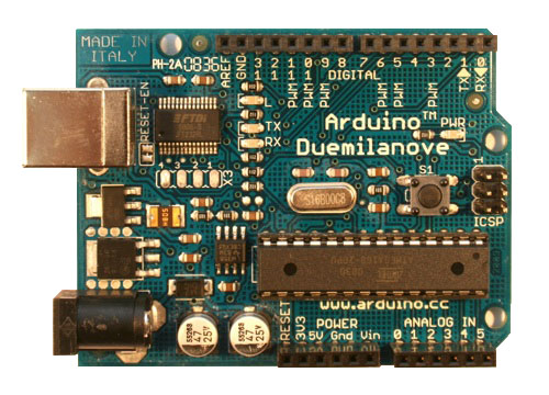
ARDUINO Duemilanove (the left image below) which basically is a microcontroller board based on the ATmega328.
ARDUINO has 14 digital input/output pins ( 6 of which can be used as PWM outputs), 6 analog inputs, a 16 MHz crystal oscillator, a USB connection, a power jack, an ICSP header, and a reset button.
It contains everything needed to support the microcontroller; simply connect it to a computer with a USB cable or power it with a AC-to-DC adapter or battery to get started.
To connecting sensors I used the
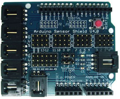
Arduino sensor shield v4.0 (the right image below) wich is placed over the ARDUINO board.


This component is not neccesary at all, I used it because it makes the connection easier, to me,
very usefull during the prototype process. I also used a
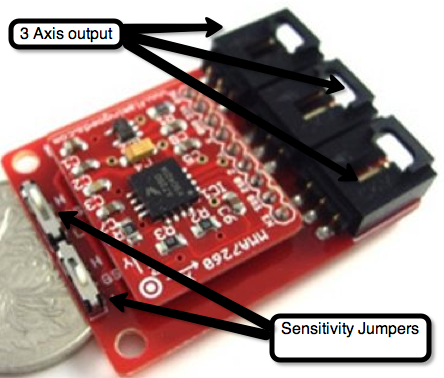
3Axial accelerometer (M616012) (see next image: the red one) to grab the hand's movements, connected directly to
Arduino sensor's shield analog inputs (A0, A1, A2). 3Axial acceleromete adapts three accelerations(Xg、Yg、Zg)and supplies four grade acceleration ranges (1.5g、2g、4g、6g). The sensitivity ranges are 600, 300, 800 200mV/g. If you wish
to change the accelerometer sensitivity, you can do that by changing the value of two little jumpers present on the top of the board (see next image).
The sensitivity range changes following the table next to the sensor (see following image).


The left and the right clicks are grabbed through 3 wires which connect two ARDUINO digital inputs (PIN 3 and PIN 4) to VCC. VCC is the wire present on the thumb, PIN 3 (Right click) is on the index finger and the PIN 4 (Left Click)
is installed on the middle finger (see the following images). Both index and middle fingers close a circuit with the thumb when the intent to clcik (right and left) on determined objcet is detected. It's like a home crafted switch
distributed on tree fingers. Obviously you have to add 2 10KH resistores from PIN 3 and PIN 4 to Ground.
The following image shows where the sensors are installed on the fingers.

The following image shows where the finger's sensors are connected to the sensor's shield. On the bottom side you see the connection between PIN 3 and PIN 4 to the ground through a 10KH resistore; you see that on the bottom of the image, which maight seem to be totally detached from the used PINS (that are on the top of the image), because
the Arduino sensor shield offers multiple PIN access ways.

MouseGlove Software
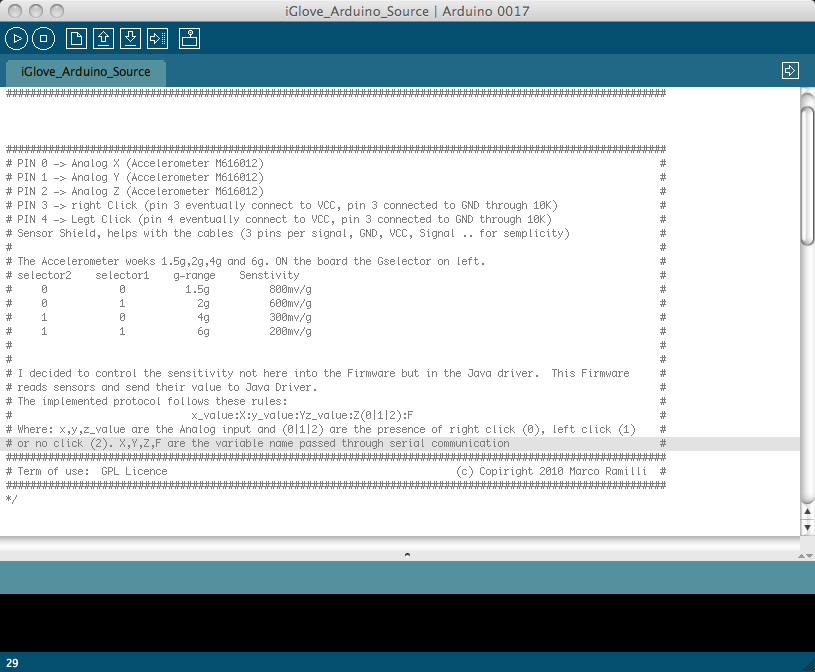
The MouseGlove software is divided into two different codes: (1) Arduino Sketch and (2) Java Software. On one hand the Arduino Sketch is a simple C program that runs under Arduino IDE (available
here) which manage the on-board digital and analog signals. It sends
through USB cable sensor's values following the protocol: X_value:X:Y_value:Y:Z_value:Z(0|1|2)F. Where X_value, Y_value and Z_value represent the analog reading from MMA7260 and (0|1|2)F represent the digital clicks. 0 right click, 1 left click, 2 no click recognized from the board.
On the other hand, the Java software takes the serial output from USB cable, decodes the previous protocol caculates the mouse pointer's coordinates and scales the acquired parameters to fit into the monitor. I developed the Java code using NetBeans IDE.
The code is well documented and very easy to understand (especially the ARDUINO Sketch ). To download the code use the left menu side.
The following images show the two enviroments to develop MouseGlove
Java code screenshot

Arduino C schellcode

Fo more information, critics, for help and so forth contact me: [ mramilli AT GMAIL dot com] .


